The customer-specific concentration can be used to convert a reference
value to a concentration value by means of a table. Max. 20 support
digits can be used for this. The curve can only be programmed with the
setup program.
The customer-specific configuration is activated in the analog input conductivity parameter.
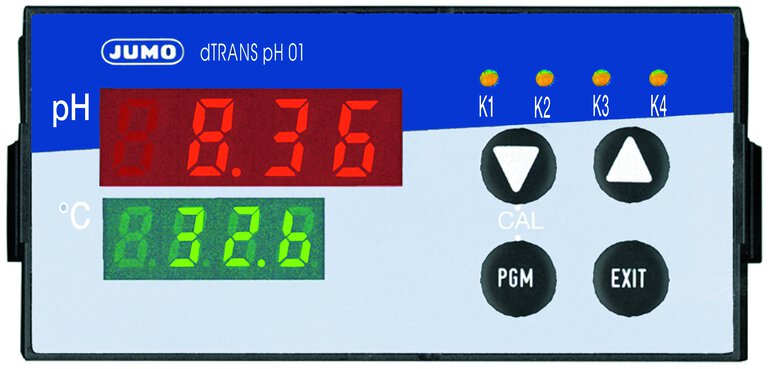
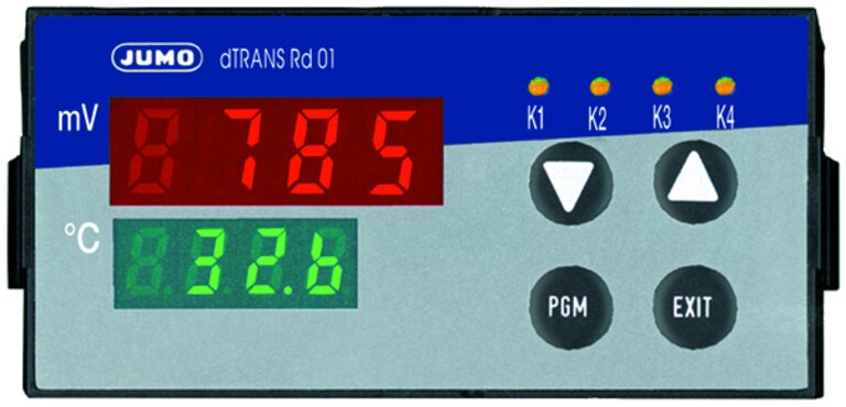
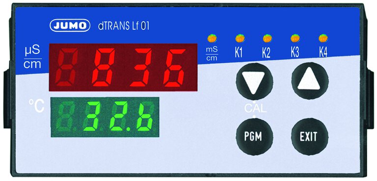
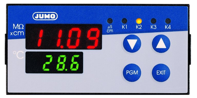
JUMO dTRANS
Frequently asked questions on analytical measurement
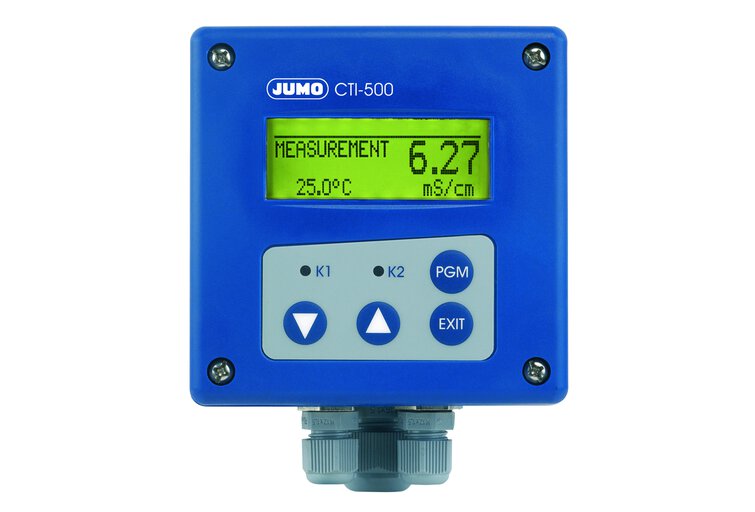
All frequently asked questions about the products Microprocessor-based transmitter/controller JUMO dTRANS pH 01, dTRANS Rd 01, JUMO dTRANS Lf 01, JUMO dTRANS Rw 01, Inductive conductivity/concentration and temperature transmitter JUMO CTI-500