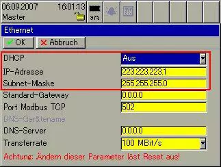
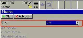
Standard setting of the LOGOSCREEN nt delivery state
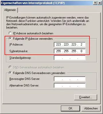
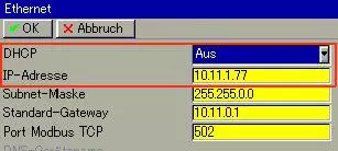
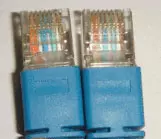
Configuration of the network card
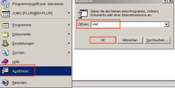
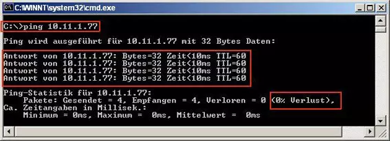
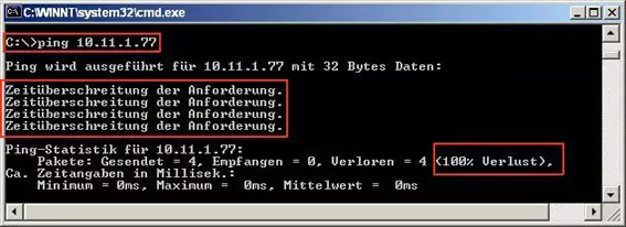
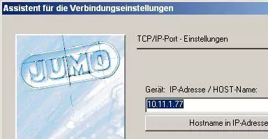
Type PING,
Then enter a space by hitting the space bar once,
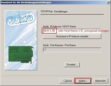
Then type in the IP address. (Example: ping 10.11.1.77)
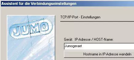
If the host name is known, a PING can also be set on it.
The command syntax consists of: PING Space Host Name, e.g. ==> ping jumo device
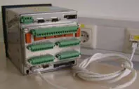
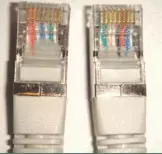
Network card LEDs and their status indicators:
Left LED (green):
Network speed
on ==> 100MB/s;
off ==> 10MB/s
Middle LED (red):
Link and activity LED
off ==> No connection;
on ==> Connected;
flashing ==> Connected and activity in the line
Right LED (green):
Operating mode
on ==> Full Duplex;
of ==> Half Duplex

a) No DHCP server in the network
b) The router operates as DHCP serverer
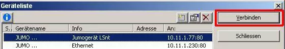
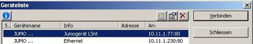
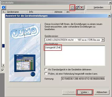
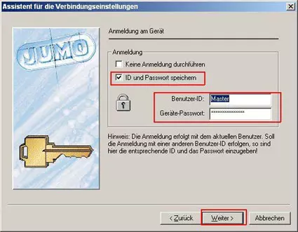
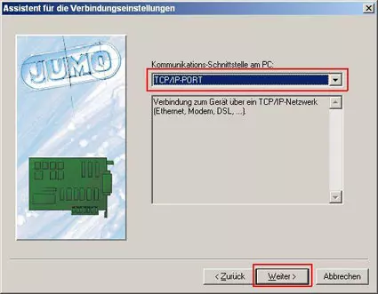
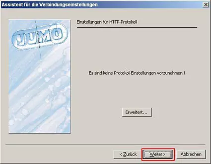
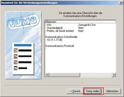
List of devices / Assistant