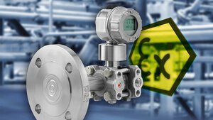
How do differential pressure sensors work? Learn more - including types, applications and information on long-term use. Find out now!
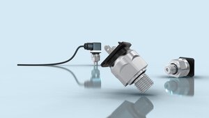
Which pressure sensor is the right one? Find out more about the different types of sensors, how they work and their design!
Absolute pressure: ✓ Definition ✓ Function ✓ Setting ✓ Use - with free practical tips. Inform now!
Hydrostatic pressure: ✓ Definition ✓ Function ✓ Setting ✓ Use - with free practical tips. Inform now!
Pressure unit: ✓ Definition ✓ Function ✓ Setting ✓ Use - with free practical tips. Inform now!
Pressure as a physical quantity: ✓ Definition ✓ Types ✓ Units ✓ Formulas - Find out now at JUMO!
Relative pressure: ✓ Definition ✓ Function ✓ Setting ✓ Use - with free practical tips. Inform now!
Static pressure and dynamic pressure: ✓ Definition ✓ Function ✓ Setting ✓ Use - with free practical tips. Inform now!