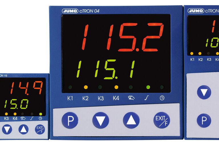
All FAQs for Basics, Startup and the products Compact controller JUMO dTRON 16.1, Compact controller JUMO cTRON, Multi-channel proceses and program controller JUMO IMAGO 500, Process controller JUMO DICON 400, 500, 501 and Compact controller JUMO dTRON 304/308/316
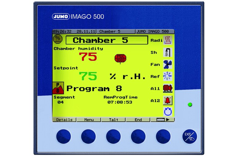
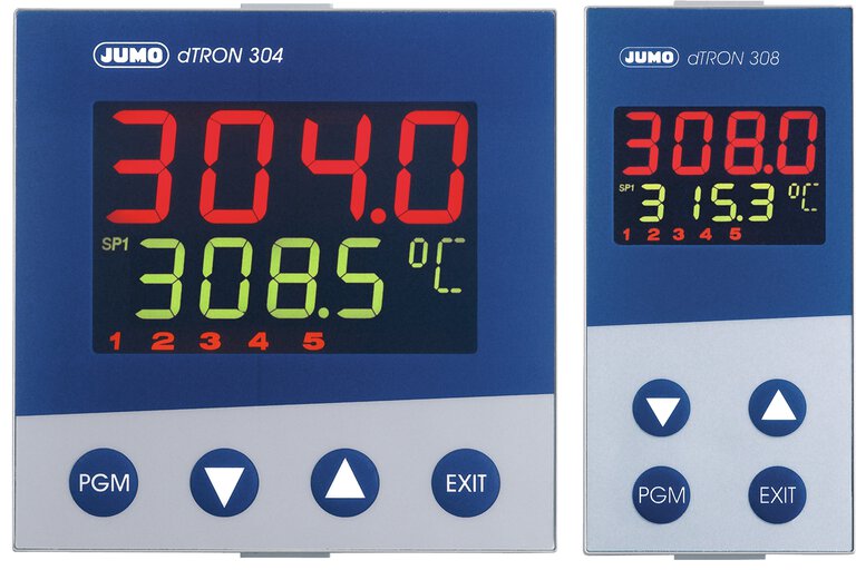
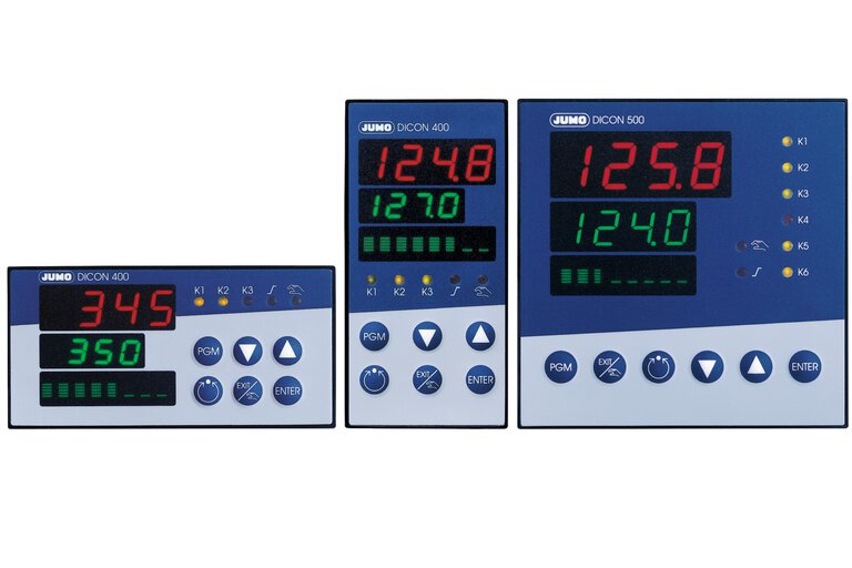
Controllers such as the JUMO IMAGO 500, JUMO DICON 500, and now the new JUMO dTRON series, include a special software tool in the setup program, for monitoring and documenting the commissioning, thus making it considerably easier.
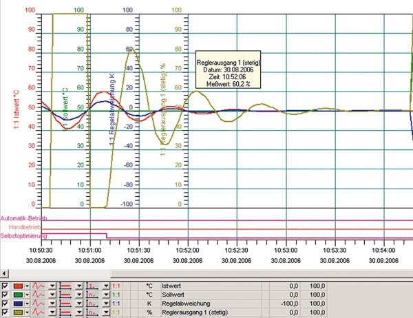
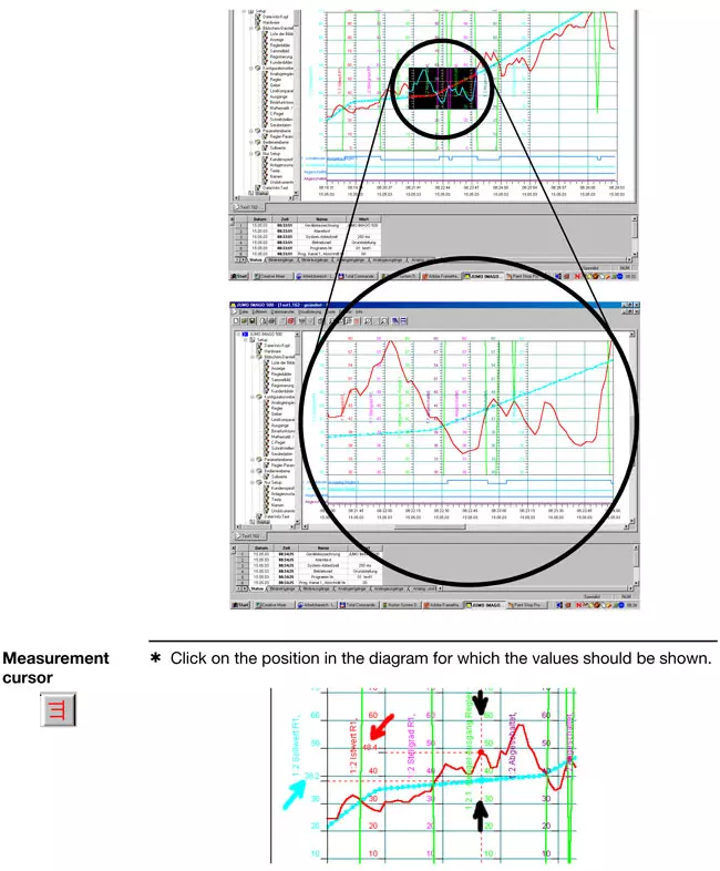
This startup software enables the visualization and storage of analog and binary signals while the system is being optimized.
Especially for complex processes, a real-time visual presentation of the most important process data is practically indispensable for the control engineer.
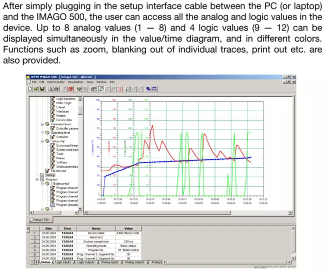
All you need for system optimization is one of the controllers mentioned above, a PC or laptop with the setup program, and an interface connection through a setup cable with an RS232 or USB interface. This connection is required anyway for the setup programming, and is therefore usually available.
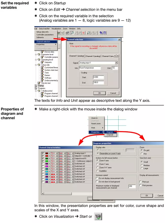
Important settings, such as the free selection of signals to display the individual analog and binary values in the instrument, zoom, various print options, showing or hiding individual curves, free scaling and choice of colors are all included in this software tool as standard.
The principal functions of the program cover:
The program is not just useful, it also provides a lot of other advantages – also economic advantages – over conventional process control monitoring, such as:
Controller optimization (or tuning) is the adjustment of the controller to a given process or control loop. The control parameters have to be selected such that the most favorable response of the control loop is achieved under the given operating conditions. However, this optimum response can be defined in different ways, such as reaching the setpoint quickly, with a small overshoot, or a somewhat longer stabilization time with no overshoot. If all that is expected of the controller is a response such as for a limit contact (without pulsed operation), there is no need to find the optimum settings for proportional band, derivative time or reset time. Only the switching differential has to be predefined.
In most cases, the controller can itself determine the control parameters through the self-optimization (autotuning) facility, if the process permits self-optimization. Alternatively, the optimum parameter setting can be determined "manually", through experiments and empirical equations (see formulae in the appendix).
When controllers are swapped, or with identical control installations, control parameters can also be directly accepted or entered.
After a manual parameter setting, autotuning may no longer be started, since this would overwrite the settings.
Formulas for setting according to the oscillation method:
Controller action |
|
P | XP = XPk / 0,5 |
PI | XP = XPk / 0,45 T P = 0,85 ·TK |
PID | XP = XPk / 0,6 Tn = 0,5 · TK Tv = 0,12 · TK |
Formulas for setting according to the step response:
Controller action | Control loop | Error |
P | XP = 3,3 · KS · (Tu/Tg) · 100 % | XP = 3,3 · KS · (Tu/Tg) · 100 % |
PI | XP = 2,86 · KS · (Tu/Tg) · 100 % T n = 1,2 · Tg |
XP = 1,66 · KS · (Tu/Tg) · 100 % T n = 4 · Tu |
PID | XP = 1,66 · KS · (Tu/Tg) · 100 % T n = 1 · Tg T v = 0,5 · Tu |
XP = 1,05 · KS · (Tu/Tg) · 100 % T n = 2,4 · Tu T v = 0,42 · Tu |
inverse: The controller output Y is larger than 0, or the relay
is energized, when the process value is smaller than the setpoint (e.
g. heating).
direct: The controller output Y is larger than 0, or the relay
is energized, when the process value is larger than the setpoint (e. g.
cooling).
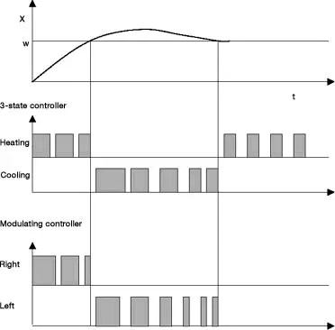
The modulating controller, like the 3-state controller, has two
switching control outputs, which are, however, designed especially for
motorized actuator drives, e.g. for opening or closing. If a continuous
output signal is required for the 3-state controller in order to
maintain a certain output level, we can see that, in the case of the
modulating controller, the electrical actuator drive will remain in the
position reached when there is no further signal from the controller.
Accordingly, the actuator drive can remain 60 % open, for example,
although it is not operated by the controller at this instant.
The digital input filter (dF) serves to dampen the input signals and affects both indication and controller. The larger the value for "dF", the larger the damping of the input signal. An extremely high or low value can have a negative influence on the control quality. In most cases, the default setting for "dF" can be used for operation.
3-state controllers have two outputs which may be either switching or
continuous (relay contact or e.g. 4 - 20 mA). 3-state controllers are
used if the control variable has to be or can be influenced through two
actuators with opposing action.
This may be a climatic cabinet with
a thyristor power unit for the electric heating and a solenoid valve
for cooling. In this example, a 3-state controller with a continuous
(analog) output for the heating function (controller output 1) and a
switching output for the cooling function (controller output 2) would be
the best choice.
On 3-state controllers, the parameters
proportional band, reset time, derivative time and hysteresis, familiar
from 2-state controllers, can often be set separately for both operating
senses. The 3-state controller additionally features the parameter
Modulating controllers have two switching outputs and are especially
designed for operating actuator drives which can, for instance, open or
close a flap valve.
Actuators/actuator drives that can be operated:
AC motor actuators, DC motors, 3-phase motor actuators, hydraulic cylinders with solenoid valves etc.
Cascade control can significantly improve the control quality. This applies in particular to the dynamic action of the control loop, in other words, the transition of the process variable following setpoint changes or disturbances.
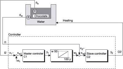
Example 1: schematic construction of a cascade
Chocolate has to be heated to vs = 40 °C for processing. The chocolate temperature must nowhere exceed 50 °C (even close to the heater). It is therefore heated on a water bath.
Cascade control is used in order to achieve rapid stabilisation.
Controller 1 is always the master controller, controller 2 always the slave.
The setpoint for the slave controller is produced by output conversion.
The control output y1 is converted to a setpoint using the unit of the process value x2 (here: 0 - 100 % = 0 - 50 °C).
List of symbols
O2 - Output 2
I1 - Analogue input 1
I2 - Analogue input 2
C1 - Controller 1
C2 - Controller 2
w
1 - Setpoint controller 1
w
2 - Setpoint controller 2
x
1 - Process value controller 1
x
2 - Process value controller 2
x
w1 - Deviation controller 1
x
w2 - Deviation controller 2
y
1 - Control output 1
y
2 - Control output 2; output 1 of controller 2
v
s - Chocolate temperature
v
w - Water bath temperature
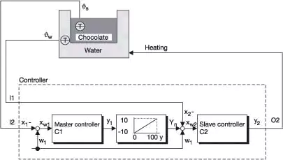
Example 2: construction of a trimming cascade
Two charges of chocolate have to be heated to 40 °C and 50 °C. The chocolate temperature must nowhere (not even close to a heater) exceed the setpoint by more than 10 °C. It is therefore heated on a water bath.
Trim cascade control is used to achieve rapid stabilisation without overshoot and without altering the controller configuration (output conversion) at a change of setpoint (batch change).
Controller 1 is always the master controller, controller 2 always the slave controller.
The setpoint for the slave controller is produced by output conversion and the addition of the master controller setpoint (w1).
In setpoint conversion, the control output y1 is converted to a value with the unit of the process value w2. It corresponds to the maximum permitted temperature difference (± | x1 - w1 |; here: 0 - 100 % = -10 to +10 °C).
List of symbols
O2 - Output 2
I1 - Analogue input 1
I2 - Analogue input 2
C1 - Controller 1
C2 - Controller 2
w1 - Setpoint controller 1
x1 - Process value controller 1
x2 - Process value controller 2
xw1 - Deviation controller 1
xw2 - Deviation controller 2
y1 - Control output 1
y2 - Control output 2; output 1 o controller 2
vs - Chocolate temperature
vw - Water bath temperature
If the process variable varies within a fixed interval about the
setpoint - the contact spacing Xsh - then neither of the outputs is
active. Exception: 3-state controllers with I and D components. Within
the contact spacing, only the proportional component is inactive.
This contact spacing is necessary to prevent continual switching
between the two manipulating variables, e.g. heating and cooling
registers, when the control variable is unsteady. The contact spacing
is also commonly called the dead band. Too small a dead band can lead
to a pointless waste of energy in a plant.
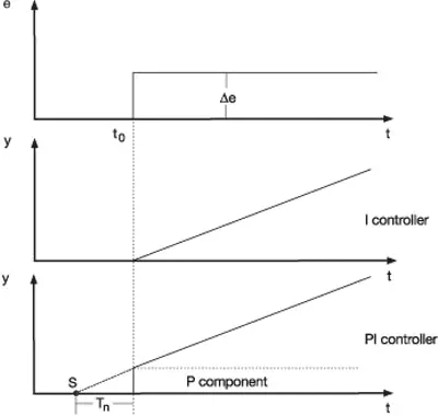
The I component of the controller output signal has the effect of
continuously altering the manipulating variable, until the process
value has reached the setpoint.
As long as the control deviation is present, the manipulating variable
is integrated upwards or downwards. The longer the control deviation
continues to be present in a controller, the larger the integral effect
on the manipulating variable. The larger the control deviation and the
smaller the reset time, the more pronounced (faster) the effect of the
I component.
The I component ensures stabilization of the control loop without
permanent control deviation. The reset time is a measure of the effect
the control deviation duration has on the control action. A larger
reset time means that the I component is less effective and vice versa.
Within the specified time Tn (in sec.), the change in the manipulating
variable that is produced by the P component (xp or pb), is added once
more. Accordingly, there is a fixed relationship between the P and the
I component. A change in the P component (xp) also means a changed
time response, at a constant value for Tn.
In a purely proportional controller (P controller) the manipulating variable (controller output Y) is proportional to the control deviation within the proportional band (Xp). The gain of the controller can be matched to the process by altering the proportional band. If a narrow proportional band is chosen, a small deviation is sufficient to achieve a 100 % output, i.e. the gain increases as the proportional band (Xp) is reduced. The reaction of the controller to a narrow proportional band is faster and more pronounced. A proportional band that is too narrow will cause the control loop to oscillate. Any alteration of the proportional band will also affect the I and D action of a PID controller to the same extent.
If the proportional band is set to zero, the controller action
is ineffective. This means that the controller operates solely as a
limit contact. The selected hysteresis or switching differential is
effective, the settings for the derivative time and the reset time,
however, are not taken into account.
For all controller types, except for the 3-state (double-setpoint)
controller, only the proportional band Xp1 is relevant. With 3-state
controllers only, separate settings for the proportional band (for both
operating senses) are necessary (e. g. Xp1 for heating and Xp2 for
cooling).
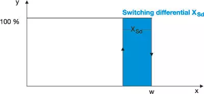
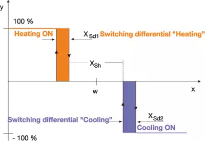
The switching differential is also referred to as hysteresis and is
only relevant for switching controllers with proportional band = 0.
For controllers with inverse operating sense (e.g. heating control), the standard response is as follows:
The switching differential lies below the setpoint. This means that the
controller switches off precisely then when the setpoint is exceeded.
It only switches on again when the process value has fallen below the
switch-on point, which lies below the setpoint by the amount of the
switching differential.
On controllers with direct operating sense (e. g. cooling), the
switching differential normally lies above the setpoint. As for
controllers with inverse operating sense, the switch-off point is
precisely at the setpoint. However, it is switched on again above the
setpoint, shifted by the amount of the switching differential.
Switching action of a 2-state controller with inverse operating sense:
Switching action of a discontinuous 3-state controller:
The actuator stroke time is a variable provided by the actuator drive
and is therefore only relevant for modulating controllers or
proportional (continuous) controllers with integral actuator driver.
The time that the actuator drive takes to travel once across the full
usable manipulation range is set under actuator stroke time.
The actuator stroke time cannot be determined by self-optimization (autotuning). It must always be set before the optimization.
The actuator stroke time provides the controller with information about
the effect of the actuating pulses. At an actuator stroke time of 20
seconds, for example, the percentage change in manipulating variable, at
the same actuating pulse, is significantly larger than for an actuator
with 100 seconds stroke time, for example.
When selecting or dimensioning actuator drives, it must be taken into
account that a short stroke time of, say, less than 10 seconds will
result in large steps of the manipulating variable, and consequently to a
reduced control accuracy. If, for example, we assume that 0.5 seconds
is the shortest actuating pulse time, a stroke time of 10 seconds would
result in only 20 actuating steps. This would mean that the manipulating
variable can only be changed in 5 % steps.
Actuator drives with a very long stroke time can, however, be
disadvantageous as far as the dynamics is concerned, because the
manipulating variable can only be changed relatively slowly by the
control action. In actual operation, however, problems arising from
stroke times that are too short occur more frequently than those caused
by stroke times that are too long.
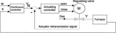
The short form "actuating controller" is used to describe a
"proportional controller with integral actuator driver". In contrast to
the modulating controller, an actuator feedback signal is essential
for the actuating controller.
The actuating controller controls the clockwise or anticlockwise movement of the motorized actuator via 2 switching outputs.
The position of the motorized actuator is registered and compared with
the manipulating variable (yR) of the proportional controller.
The intensity of the D component (differential component) can be set via the derivative time. The D component of a controller with PID or PD action reacts to the rate of change of the process value.
When the setpoint is approached, the D component acts as a brake, thereby preventing the control variable from overshooting the setpoint.
Basically, the D component has the following effects:
As soon as the control variable changes, the D component reacts against this change.
For a controller with an inverse operating sense (i.e. for heating) this would mean, for example
The 2-state controller (ON/OFF controller) switches the output when the
setpoint is reached. If the value falls below the setpoint by a
certain adjustable tolerance (xsd, switching differential, hysteresis),
then the output is switched on again. It therefore only has two
switching states. It is used in temperature control applications where
the heating or cooling is only switched on or off.
A 2-state controller with dynamics can, however, also operate with a P, I, or D component.
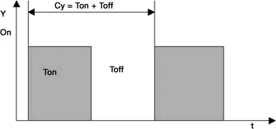
The switching cycle time is quoted in seconds and defines the period during which a full switching cycle consisting of switch-on and switch-off times takes place.
Generally, the cycle time should be selected so that the actual
control process can still be smoothed out. At the same time, the
switching frequency must always be taken into account.
The response can best be reset in manual mode so that the direct
influence of the manipulating variable on the cycle time can be
monitored. With a manipulating variable of 50 %, "Ton" and "Toff" are
equal. If the manipulating variable is altered, this ratio alters
accordingly.
If '1999' flashes, this means that either no measurable signal is
present (probe break) or the configuration under C111 is incorrect.
1. Check the measurement signal (resistance measurement, current/voltage
measurement), if necessary, define values using a signal source.
2. Check configuration code C111 (default setting Pt100, Chapter 7.1 of the Operating Instructions).
On a standard universal input (resistance thermometer, thermocouple, current) the solder links S101 and S102 on the CPU board are assigned as follows:
If input 1 has to operate off 0 - 10 V (other signals are then no longer possible!), the solder links on the CPU board must be changed as follows:
Assignment of links for input signal 0 - 10V for input 1:
A PC setup program for configuring the controller from a PC is available for the dTRON 16.1. As well as the PC program, JUMO Part No. 70/00400027, you will need an interface cable with a special adapter for the dTRON 16.1. The JUMO Part No. for the interface cable is 70/00400821.
The analog output (output 3) is an optional output and is not fitted in the standard instrument. If the output has been included in the order, then the output signal can be changed between current and voltage by means of solder links on the output board. The signal start 0 or 2 V, or 0 or 4 mA, is set at the configuration level C 114.
It can be seen from the type designation whether a dTRON 16.1 with an analog output has been supplied. Please refer to the operating instructions, chapter 2 “Identifying the instrument version”.
The following two solder links on the analog output board must be altered accordingly when changing between current and voltage signal:
Output signal range | Solder link S 602 (S1) | Solder link S 602 (S2) |
0/4 - 20 mA | open | open |
0/2 - 10 V | closed | closed |
Depending on the selected controller type, the following parameters are determined through autotuning:
Controller type | Parameter |
2-state controller ON/OFF function | Pb1, dt, rt, Cy1, df |
3-state controller | Pb1, Pb2, dt, rt, Cy1, Cy2, df |
Proportional controller | Pb1, dt, rt, df |
As soon as autotuning is started from the “Exit“ key (hold down for 2 sec), the controller attempts to determine the time response of the process by applying step changes in the manipulating variable. Autotuning evaluates the development of the process value resulting from these changes in the manipulating variable and calculates the controller parameters. During autotuning, you will see “ tune “ flashing in the bottom display.
On termination of the autotuning procedure, “ tune “ ceases to flash.
The duration of the autotuning procedure depends on the time response of the controlled process. If the process reacts relatively quickly to the changes in manipulating variable, then autotuning may be over in a matter of seconds or minutes. With slow processes, autotuning may take half an hour or longer.
With the cTRON 04 and 08, you can use the setup program hardware assistant to activate a second binary input.
The analog input can then no longer be used to acquire a 0 - 10V signal. The analog input is still fully available for the other input signals, such as Pt100, thermocouple and current.
There is a 30-day test version available for testing the setup program.
All setup program functions can be used without restriction for 30 days
after the initial installation. Setup data transfer, storage and
startup are automatically disabled after 30 days.
To enable the setup program functions (even after the 30 days) without a time limit, enter a license number.
You can load the program from the JUMO Website:
You have to create a new document (File -> New). Then you can choose whether the setup program should automatically detect the device hardware configuration or whether you want to set up the device hardware configuration manually.
It is possible to use the 0/14V logic output for this purpose. You can use the setup program to invert the output that has been switched off. This sets the logic output permanently. This function can be implemented with a limit comparator, for example, without the setup program.
Before using the logic output for the transmitter supply voltage, you must check whether the available voltage of about 14V is sufficient for the transmitter power supply and the voltage drop via the cable and the measurement inputs.
To reset the JUMO cTRON to the JUMO factory settings, press “P” and
the “Up Arrow key” simultaneously when the power is switched on.
“IniT” will briefly appear in the lower display.
Caution!
The function should only be used if you have the full
application-specific configuration or if all the controller requirements
for the particular application are known in detail. Third party default
settings (made by equipment manufacturers, for example), will be reset
to the JUMO standard and will thus be lost
If this error message appears, there are several possible causes.
The following points should be checked:
The preconditions for starting the autotuning function of the JUMO IMAGO
500 are that the device is in the basic status and autotuning has been
enabled in the configuration level.
The output that is to be optimized must be set correctly (e.g. relay /
analog output / solid-state). See Operating Instructions B 703590
”Controller 1 (2...4) > Autotuning”.
Activating the Exit/Hand button for > 2seconds switches the program
controller over to ”Manual mode”. Use the UP/DOWN button to enter the
required value for the setpoint, and confirm with ENTER.
Activating the buttons and then
produces the
button, which can be used to start the autotuning and stop it again.
The use of this softkey/button combination only optimizes the channel
that has been selected for display.
To alter the setpoint value for the program controller, in the basic status, proceed as follows:
First press the softkeyand then the softkey
. The
button will then appear, which you can use to alter the setpoint in the basic status.
If the date and time need to be set, this can be done either directly on
the Imago 500, in the menu item ”Configuration > Device data >
Date and time”, or in Setup, under the menu item ”Extras > Date and
time”.
The transfer of the date and time is made regardless of any Setup data transmission.
The sampling time can be set in the Setup program, in the menu item ”Device data”.
A time of 50, 150 or 250 milliseconds can be selected, according to the application.
The actual sampling time that will result can differ from the preset sampling time.
On the Imago 500, you can see the true sampling time in the menu item
”Menu > Configuration level > Device data > System sampling
time”.
This system sampling time cannot be programmed directly, but can only be
influenced by the number of functions that must be performed and the
number of controllers.
The user level is an additional level that will only be visible when it has been configured. Up to 8 application-specific parameters can be shown here, and edited within this level.
In the Setup program, under the menu item ”Display” - ”User level”, you can select the parameters for the user level by entering the addresses and defining customer-specific names for them.
Caution! For Float parameters you must take the corresponding address +1
(e.g. Limit comparator for threshold Al 1, address 0x026F +1 = 0x0270)
Note: This only applies up to and including device version 162.02.05
Changing the device language must be carried out in two steps.
In the first step, the required language is selected and transmitted to the device, using Setup and the Device Assistant ”Edit > Hardware”.
In the second step, the required language is selected for the item "Extras > Device texts library" and transmitted to the device, using the ”Transmit” button.
This change will only take effect after the device has been switched off and then switched on again.
In the standard version, the unit of measurement is set to °C. If a
different unit of measurement is required, it can be set through the
Setup program, for the appropriate ”Analog value”, in the menu item
”Controller pics”.
In the section ”Unit”, the required measurement unit can be entered in the item ”Text”.
There are several device options (math, controller 3+4, C-level, recording) that can be enabled through the Setup program, using a release code.
In order to be able to access these options, the device must be online. In the Setup program, go to the ”Extras” menu in the task bar, and then to the item ”Enable device options”.
Activating ”Read code” opens a further window, in which the required options are marked:
Pressing the ”Generate code number” button will produce the required code numbers that you will need when you call the correct phone or fax number.
You will be given a release code that you can enter in the appropriate field, using the ”Enable” button.
Caution! The code number may be given with a mathematical sign.
A time-dependent programming can be implemented with the Imago 500.
If a gradient is needed, then the rate of change must be converted to
give a value for the time period.
If, for instance, the setpoint is supposed to change from 10°C to 100°C
at a rate of 5°C per minute, then the following conversion is required:
Setpoint change of 90 °C / 5 °C per minute = 18 minutes for the complete ramp.
In a similar way to the device options, there are a number of program
options (Startup, Teleservice, Program Editor) that can be enabled for
the Setup program.
Under the menu item ”Extras” – ”Enable program options” you can enter your license number to enable the function you need.
You can obtain the license number from the central order processing department of JUMO in Fulda:
Phone: +49 661 6003 723
Fax: +49 661 6003 509
If the IMAGO 500 is equipped with a PROFIBUS interface that is not yet
used, then the error message "PROFIBUS-DP ERROR" will appear on the
display.
This error message can be suppressed by entering the PROFIBUS device address "0" directly from the keys of the IMAGO 500.
From setup program version 162.03.xx 3.00(J) upwards, you can also use a PC to set the PROFIBUS device address to "0".
Alterations to the settings in the Imago 500 can be made faster,
using the Setup program, if you do not have to transmit all the data,
but just the data for the section that has been changed.
To do this, the Imago 500 and the Setup program must be ”Online”.
In the dialog area, use the right mouse button to click on the field
that has to be altered, and then select the menu item ”Edit display
online”.
The currently valid settings will be read out and displayed. When you have finished editing and quit this menu item, the altered data for this section will automatically be transmitted to the Imago 500.
Recording is a device option that must be enabled in order to be used.
Recording will be started as soon as this function has been enabled and the device is connected.
You can select the required signals (e.g. process value, setpoint,
control deviation etc.) either via the Setup program, or directly from
the controller, in the menu item ”Recording”. These signals will then be
subsequently recorded on the display, just like on a conventional
recorder. The recorded time span depends on the sampling rate (which is
adjustable) and can vary from about 12 hours to a maximum of 24 hours.
A subsequent release of the maths- and logic option can be realized via setup program to the Dicon 40x/50x and interface connection to the controller.
For release of this option it is not essential that the controller is fully wired; only the voltage supply of the controller must be connected.
The interface connection can be easily realized with a JUMO USB-TTL-Interface or with a JUMO RS232-TTL-Interface via the standard programming interface of the controller.
Alternatively to the JUMO interface connection an optional interface RS485/RS422 can be used for connection establishment.
Access to the menu for the release of maths- and logic option via menu “Extras” - “Release of additional codes” . Before acccess to this menu, please open a setup file (e.g. via menu “File” – “New”.
With “read-out code number” the code number is displayed – for a release of the above mentioned options JUMO must be provided with this code number.
The generated code number incl. possible sign, can be provided by E-mail, fax or phone. Upon receipt of this number, JUMO generates the release code and informs you accordingly.
Please put in this release number you get from JUMO as follows:
The release of maths-/ logic option is completed upon input and confirmation of the release code.
In order to edit the corresponding maths- or logic formula in the setup program, you either need to re-start the automatical identification or to adjust the released option manually under “Hardware”.
The available options for the measurement range depend on the hardware configuration.
This can be changed by altering the positions of two jumpers.
For the ranges -10 / 0 / 2 - 10 V, the jumpers on the CPU board (inputs 1
and 2) or the input board (inputs 3 and 4) must be set as follows:
CPU board
Input card:
Note:
Making settings through the setup program will only be possible if the jumpers have been set accordingly.
The JUMO DICON 400/500 or 401/501 provides the option of programming up to 8 such limit comparators.
In order to make the best use of a limit comparator, it must be programmed for the required switching response.
The switching response is defined by the limit comparator functions (lk 1 - lk 8).
lk 1 - lk 6 are functions based on the setpoint, and lk 7 - lk 8 are based on fixed limits.
For lk 1 - lk 6, the AL (alarm level) is the difference between the setpoint W1 and the switch-on or switch-off point.
For lk 7 - lk 8 the AL is an absolute limit value at which the contact will switch on or off.
Example:
Function lk 8 > limit value 70 °C, the assigned output remains
switched on unless the process value rises above 70 °C, whereupon it is
switched off.
If the process value falls below 70 °C, the output is switched on again.
The return switch-on point can also be controlled by a switching differential.
In this level you can test the display, keys, switching outputs, and so on.
SERVICE
The matrix display shows alternately "Code-NR." and "0000". Use the <Enter> key to move one digit to the left, use the arrow keys to set "7", and press the <Enter> key 3 times.
ANZEIGE
All the displays will be lit up.
KEYS
The keys that are pressed will be indicated in plain text in the matrix display (display 3).
LOGIC IN
The matrix display indicates "00000000". Setting the logic inputs to "0" (e.g. by closing a contact) changes each one of the zeroes to a "1", e.g. "11111111" (depending on the version fitted).
RELAYS
Outputs 1 - 6 <Enter> à For switching outputs (relays, solid-state relays, logic): the outputs can be switched by using the arrow keys. When the keys are released, the relays drop out again.
This test function has no effect for analog outputs or logic inputs.
INTPT100
The matrix display shows alternately "Temp" and the cold-junction temperature measured at the moment (for thermocouples, in the back panel).
SCHNITTS (interface)
The device shows the count of the number of commands received in the upper display (display 1).
In the middle display (display 2), the device shows the count of the number of commands sent.
Note:
On devices that only communicate via the setup program, both counts must be identical. The <Enter> key can be used to reset the count to "0".
The individual registers offer various test options for outputs, keys etc.
Important:
You must not alter any values in the register card Calibration constants.
If you do this nevertheless, the calibration data will be partially or
completely lost, and the controller will have to be returned to the
main factory for recalibration.
The controller output types must be defined before self-optimization can be started.
When the device is used as a program controller, the <Exit/manual>
key must be set to manual mode. Then use the arrow keys to set a
setpoint that is close to reality for the process, and confirm with the
<Enter> key.
Now press the following keys simultaneously: <PGM> + <Automatic>.
The self-optimization will stop by itself.
It can also be canceled by using the key combination <PGM> + <Automatic>.
For the value entry, a whole number is entered first.
If a decimal point position is necessary, this can be moved up or down (i.e. to left or right) by using <ENTER+UP> or <ENTER+DOWN>. In this case, the last decimal place must be a zero.
Note:
The decimal point is only present if the decimal place has been programmed for the display configuration. If this is not done, then the controller will round the entry up or down.
So there is a distinction made between the display and the value entry.
If, for instance, the setpoint is configured for the display with just a single decimal place, then a value that is entered with two decimal places will be rounded up or down to give only one decimal place.
You can only use the external relay module in conjunction with the setup program.
The control function for the relay modules is activated by placing a
tick mark for "Activate relay module" in the extended configuration.
Only when this has been done will the setup program provide the option of assigning functions to the ER8 external relay module,
for example: Relay function 1 : Controller output 1/ Relay function 2 : Limit comparator 1
PT100, 3-wire
For testing, link terminals 10 and 11 of input 1, and connect a fixed resistor or resistance decade between 9 and 10.
Value of resistor / resistance decade setting |
Display value |
18.52 ohms | -200 °C |
100 ohms | 0 °C |
109.73 ohms | 25 °C |
390.481 ohms | 850 °C |
Thermocouple
For testing, link terminals 10 and 11 of input 1.
If the input is working correctly, the controller will indicate the ambient temperature.
Current/voltage input
For testing, configure input 1 to 0-20mA or 0-10V.
If the input is open-circuit, the display will indicate the lower scaling value (start of display range).
If a 20 mA or 10 V source is connected, then the upper scaling value
(end of display range) will be indicated. As standard, this corresponds
to 0-100 %.
In general, only the 500/501 provides the option of retrofitting up to 2 inputs.
These can only be inserted in the slots A and B, which are reserved for this purpose.
You will need a converter from RS232 to Profibus DP
Start the JUMO GSD generator…
Move the measurement values for analog inputs 1+2 into the "PLC input" field.
"File" à "Diagnosis" à "Settings"
Set the slave address and the COM port à "OK"
"Online"
The values will now be shown in the value field:
If the device is used as a process / fixed setpoint controller, the controller output level is preset when manual mode is used.
If
the device is used as a program controller, a fixed setpoint is given
when using manual mode, and the controller regulates to this setpoint.
If
the <Exit/Hand> key is pressed while the program is running, a
temporary setpoint change can be programmed. This will only be effective
for the program run taking place at the moment. After a new program
start, the values that are defined in the program editor will apply.
You can either enter the setpoints and times directly on the device,
or use the PC program to write a program file that is transferred to
the device.
This is a programming example for the following program profile:
Writing (i.e. entering) the profile on the device (example)
Segment number | Setpoint | Segment time |
01 | 0 | 00:10:00 |
02 | 100 | 00:10:00 |
03 | 100 | 00:10:00 |
04 | 0 | 00:00:01 |
Writing the profile as a program file, on the PC (example)
A 30-day test version is available for testing the software.
This version of the setup software can be used without restrictions.
Data transfer, storage and Startup can be tested for 30 days from the date of the software installation.
After this time, the 30-day license expires automatically and can only be enabled by an original license.
When the interface is selected on the instrument, the display shows “r422” for MODbus, and “ProF” for Profibus-DP.
Because of the display representation limitations, the display has been
restricted to “r422” for the MODbus interfaces. However, configuration
under this parameter also includes the RS485 interface. From the
connections to the terminals, the instrument hardware can detect whether
the RS422 or RS485 is being operated.
To be able to start self-optimization using the key combination UP+DOWN, following prerequisites must be fulfilled:
The maths and logic option can be activated later using the setup program for the dTRON 300 series and an interface connection to the controller.
Complete wiring of the controller is not required for activating the options. It is only necessary to connect the controller voltage supply.
The interface connection can easily be established with a JUMO USB-TTL or JUMO RS232-TTL interface and the serial programming interface.
An optional RS485/RS455 interface can be used for establishing the connection as an alternative to the JUMO interface lines.
The menu used to activate the maths/logic option is invoked via "Activation of extra codes" under "Extras".
Ensure that the online mode is activated in the setup program beforehand. The activated online mode is indicated by the current status information or the measured values at the bottom of the mask and the active symbol for "Disconnect connection".
The maths option, also including the logic option, then can be selected in the menu behind the "Read out code number" button.
The menu used to activate the maths/logic option is invoked via "Activation of extra codes" under "Extras". Ensure that the online mode is activated in the setup program beforehand. The activated online mode is indicated by the current status information or the measured values at the bottom of the mask and the active symbol for "Disconnect connection".
The activation of the options is completed when the activation code is entered and confirmed. To allow the maths or logic formulae to be subsequently edited in the setup program, start the automatic detection program once or manually set the activated option under "Hardware".
Accidental or wrong entries under FTS and FTE have resulted in an increased number of complaints. For this reason, these parameters (for customer-specific fine tuning) have been removed from the standard menu guidance from version 192.02.04 onwards.
If required, they can be enabled via Undocumented parameters in the setup program.
Bit parameter 17 must be set under the item Undocumented parameters.
Up to device software version 192.01.02, the logic outputs had the
highest priority. (When the logic outputs 3/4 were configured from the
instrument, then binary inputs 1/2 were hidden.)
From device software version 192.02.02 onwards, the action is reversed:
Now the binary inputs have the highest priority, and when the binary
inputs 1/2 are configured, the logic outputs 3/4 are hidden.
From version 192.02.xx 2.03, a note for the users of the setup program is switched into display.
The following keys can be used to reset the controller to the factory default settings.
Keep PGM and EXIT pressed down simultaneously at Power ON.
“IniT” will appear briefly in the display.
Caution!
The controller now operates with the JUMO default settings.
The plant manufacturer's presettings, or customer-specific settings, have been deleted.
Output level limitation is effective in two distinct ways: In manual
mode, the output level limits that have been set in the active parameter
set are effective.
In automatic mode, the output level limits in the active parameter set
are only effective if the corresponding proportional band (Pb1/Pb2) has
been set larger than zero (e.g. to 1).
The operating concept has become more user-friendly from device software version 192.02.03.
The most important modifications are:
Because of the modified operating concept, the user level (if configured) can be accessed by pressing the PGM key twice.